What Are the Subsystems of Structured Cabling and What Does Each One Solve?
Structured cabling has six subsystems, from the entrance facility to the work area. What each one solves in a plant and why the backbone should be fiber.
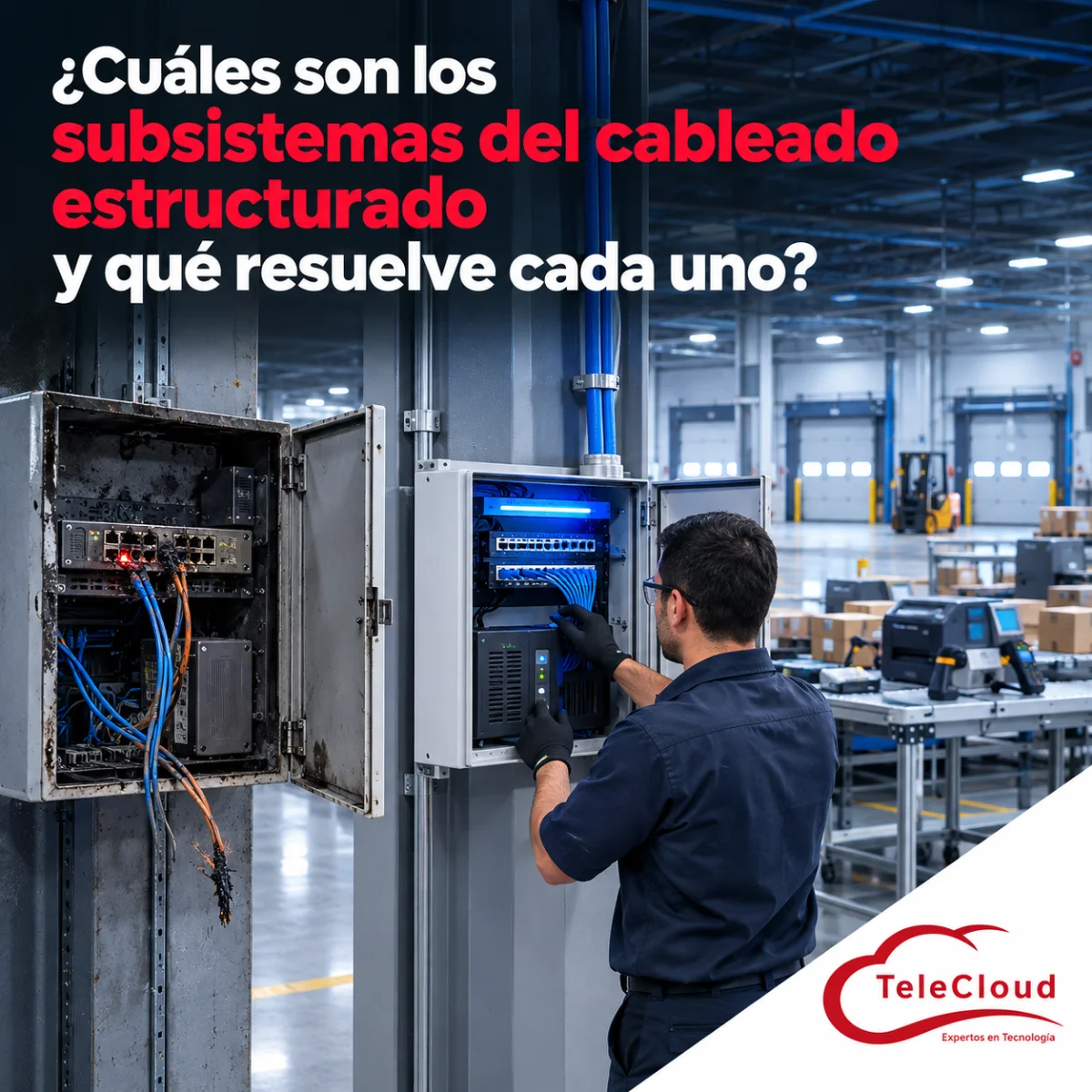
The plant grew with a second building on the other side of the yard. To connect it quickly, someone ran a copper cable through a buried conduit from the office to an enclosure bolted to a column, with no backup power, and from there distributed the network to the packing stations, the label printers and the dock scanners. The internet connection came in at the security booth and continued above the ceiling to a rack in the IT office, next to the traceability system server. A lightning storm induces a surge on the cable across the yard: switch ports burn out in both buildings and the server loses its connection to the production floor. Packing stops, the docks stop printing labels and the day's shipments leave hours late, with the traceability record put together by hand. Replacing the equipment takes an afternoon. Reconstructing the path of every cable, with no drawings or labels, takes the rest of the week.
TIA-568 and TIA-569 divide cabling into six subsystems: entrance facility, equipment room, backbone, telecommunications room, horizontal cabling and work area. Each one solves one section of the network and contains its failures.
Six subsystems that an improvised network mixes up without noticing
TIA-568 sets the cabling requirements for each subsystem, and TIA-569 defines the spaces and pathways that house it. Each subsystem is designed, tested and modified separately, so a layout change on the production floor leaves the backbone intact and a failure in one section stays contained in its zone.
The plant in the opening had cabling and it had a network. What it lacked were boundaries: the entrance facility ended in a security booth, the equipment room was an office, the backbone between buildings was an exposed copper cable and the telecommunications room in the second building was an enclosure with no backup power. Together, those shortcuts turned a storm into a plant-wide shutdown.
The subsystems that connect your plant to the outside and support it from the center
Entrance facility: where the provider ends and your network begins
The entrance facility is the point where cables from telecommunications providers enter the building, along with the backbone cables coming from other buildings on the campus. That is where the demarcation point sits, the boundary of responsibility between the provider and your company, and where outside plant cable, designed for conduits and outdoor use, transitions to cable rated for indoor use. Copper conductors coming in from outside carry surge protectors bonded to the telecommunications ground.
If your operation depends on the internet, it makes sense to plan for two service entrances along physically separate routes. If the two links you contract enter through the same conduit, a trench dug by a neighboring construction project cuts both at the same time.
Equipment room: the center of the network, with conditions of its own
The equipment room houses the core switch, the servers, the firewall, the phone system and the video recorders, along with the main cross-connect from which the backbone starts. TIA-569 requires the conditions of a technical space: controlled access, cooling sized for the load, backed-up power, grounding, room to grow and a location away from water pipes and transformers.
An IT office with a rack in the corner does the job until the first incident: a comfort air conditioner that shuts off over the weekend, a leak from the floor above or a visitor who unplugs a cable. Because everything depends on this room, any of those incidents stops the entire plant.
The backbone: the subsystem that decides whether a failure stays in one zone or stops the plant
Backbone or vertical cabling: the spine that links the rooms
The backbone, also called vertical cabling because in office buildings it rises between floors, links the equipment room to the telecommunications rooms and to the entrance facility. In a plant, it usually runs along the length of the building or between buildings, as a campus backbone. The standard organizes it as a hierarchical star, with a maximum of two levels of cross-connects, so the failure of one section affects only the zone it serves.
Fiber optics in the backbone: immunity to noise and surges
In manufacturing, the backbone is almost always built with fiber optics. A dielectric fiber cable has no metallic conductors, so it is immune to noise from variable frequency drives and motors, does not carry surges between buildings and covers distances beyond the 100 meters that limit twisted-pair copper. Multimode is used within a building and single-mode on long runs between buildings. In the plant from the opening, a fiber backbone would have kept the storm out of the network.
A backbone is designed with the next ten years in mind, with spare strands and dedicated pathways, because opening a new route between buildings costs much more than the extra strands.
Telecommunications room: the distribution point for each zone
The telecommunications room concentrates the termination of a zone's horizontal cabling and connects it to the backbone. It holds the patch panels, the access switches and, in a plant, the UPS that keeps the zone's PoE devices running during an outage. Its location is set by distance: every outlet must be 90 meters of cable or less away, counting rises, drops and detours. In a large building, that usually means several rooms or enclosures, each with its own fiber link to the equipment room.
On the production floor, the room usually takes the form of an enclosure mounted on a wall or a column. The standard recognizes that arrangement, and TIA-1005 adds criteria for the industrial environment, such as protection against dust and liquids and the ventilation each zone requires. An enclosure with no backup power or grounding, like the one in the second building from the opening, turns every power outage into a network blackout for the entire zone.
Where the network meets production: horizontal cabling and work area
Horizontal cabling: the most exposed section of the entire installation
Horizontal cabling runs from the patch panel in the telecommunications room to each outlet, in a star, one cable per outlet, with no splices or taps and with the 90-meter permanent link limit. It is the subsystem with the most points and the one that gets modified most often: every layout change, every new machine and every additional camera goes through it.
In a plant, it also runs through zones with electrical noise, heat, vibration and forklift traffic. That is why it is specified zone by zone, with the cable category, shielding and jacket each environment calls for. For areas whose configuration changes often, the standard allows a consolidation point: a fixed intermediate connection from which outlets can be relocated without pulling a new cable all the way back to the room.
Work area: from the wall to the machine
The work area starts at the telecommunications outlet and ends at the device: the computer, the IP phone, the label printer, the camera or the access point, with its patch cord. On the production floor, it concentrates a large share of the problems: patch cords crushed under pallets, outlets without covers in washdown areas and connectors that work loose from the vibration of a press.
TIA-1005 extends the work area all the way to the machine, with outlets inside control panels or in automation cells, sealed connectors and patch cords with industrial jackets. It pays to define at the design stage which device connects to each outlet and to leave spare outlets, because every point added later costs a site visit, a work window and a new cable.
The mistake of solving each subsystem on its own
The six subsystems share three elements that are designed for the entire installation at once. The TIA-569 pathways connect the spaces with dedicated, protected routes. The TIA-607 grounding and bonding ties the entrance facility, the equipment room and each telecommunications room into a single system, so a surge reaches ground before it reaches the equipment. The TIA-606 administration standard assigns every cable, port, rack and pathway a unique identifier that appears on the label and on the drawings.
When each subsystem is handled by a different contractor, those three pieces are left half done: the backbone enters through a conduit that is already full, the ground of the new enclosure is never bonded to the busbar in the main room and the labels follow three different conventions. That is why, in the opening, rebuilding the network map took longer than replacing the equipment.
How we design your plant's subsystems at TeleCloud
At TeleCloud we start with an on-site survey: we locate where the providers come in, measure the actual distances, review the existing pathways and define where the equipment room and the telecommunications rooms go. With that, we design all six subsystems under TIA/EIA standards as a single project.
We fit out the telecommunications room with a rack, pathways, grounding, backup power, cooling and labeling; we install the fiber backbone with dedicated pathways and spare strands, and we install the horizontal cabling with our own staff, in phases and during the windows we agree on with production. At closeout we certify every link and deliver the technical documentation, the drawings and the per-point report.
If your plant's network grew through shortcuts, every missing subsystem is a point where a small failure can stop the entire operation. At TeleCloud we design, install and certify all six subsystems as a single project, with our own staff and in phases, without stopping your production. Request a diagnosis of your network
Frequently asked questions
Does my plant need a separate equipment room and telecommunications rooms?
In a small plant, a single space can serve both functions if every outlet is within 90 meters of cable and the room meets the access, cooling and power requirements. If the plant has several buildings or more distant zones, it needs one telecommunications room or enclosure per zone, linked to the equipment room with fiber.
Can I use copper cable to connect two buildings?
Only over short distances and with surge protection at both ends, and even then it is the least advisable option. Between buildings, copper is exposed to ground potential differences between the two buildings and to surges from storms, in addition to the 100-meter limit. Fiber optics eliminates those risks and leaves capacity to grow.
Which subsystem should I check first if my plant's network fails intermittently?
The horizontal cabling and the work area, because they concentrate most of the points and the exposure to the production environment. If the failures affect an entire zone at once, the next suspect is its telecommunications room or its backbone link. Certifying the links and inspecting the rooms narrows down the problem before you replace any equipment.
Do you need a network diagnosis?
The TeleCloud team evaluates your current infrastructure and proposes solutions adapted to your industrial operation.
Schedule free diagnosis