
What Does the TIA-568 Standard Require, and Why Should Your Installation Comply With It?
TIA-568 defines how structured cabling is designed, installed, terminated and tested. We explain the structure it sets out, the installation details that decide whether a link passes certification and the documentation a customer's auditor will ask you for.
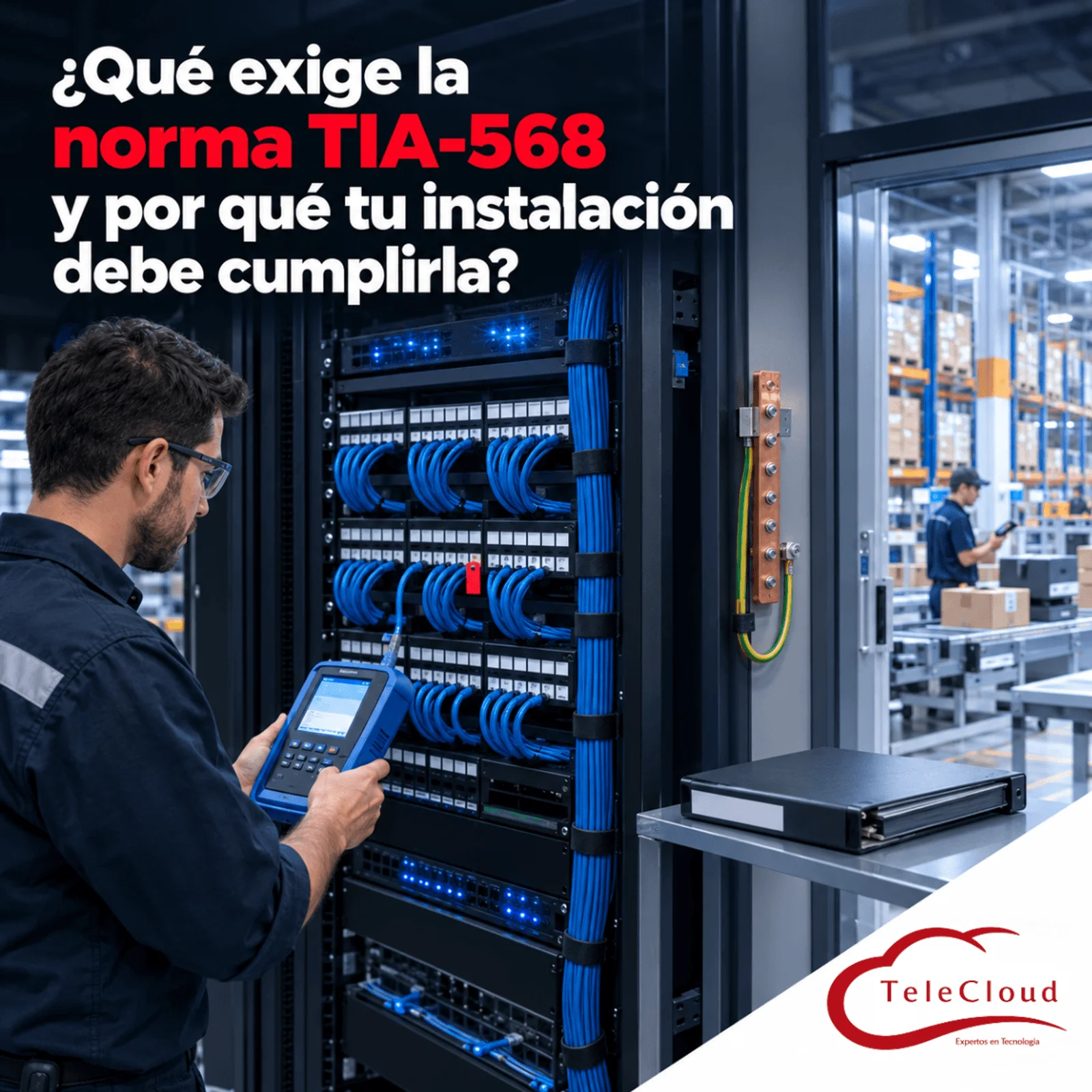
The new warehouse was delivered on time. The construction contractor ran the network cabling along with the electrical installation, connected each drop to a continuity tester and reported that they all lit up. Six months later, with the RF terminals and label printers in operation, intermittent outages begin. The certification nobody had done reveals the full picture: runs longer than 100 meters, cables spliced with tape above the ceiling, connectors terminated with a different scheme at each end, switches hidden in cascade on top of the product racks and not a single label. That same week, the auditor from an automotive customer asks for the infrastructure documentation, and there is nothing to hand over. The plant ends up paying twice for the same cabling, the second time with the warehouse in full operation.
TIA-568 defines how structured cabling is designed, installed, terminated and tested. Complying with it gives you a network with verifiable, documented performance that supports several generations of equipment and stands up to an audit.
What you risk when your cabling is installed without a reference standard
ANSI/TIA-568 is the Telecommunications Industry Association standard that sets the requirements for telecommunications cabling in buildings. It is the most widely used design and installation reference in the Americas, and its international equivalent is ISO/IEC 11801. Its central principle is generic cabling: an infrastructure designed independently of any single application or equipment manufacturer, able to support telephony, data, video and control systems through several generations of switches. Cabling installed without that reference works as long as nothing changes, and nobody can predict what it will support when the next piece of equipment arrives.
A family of standards: what each part covers
TIA-568 is published in several parts that are revised periodically, and each revision adds a letter to the name, which is why you will see references such as TIA-568-C.2 or later versions in project documentation. Part 568.0 sets the general requirements for any type of premises; 568.1, those for commercial buildings; 568.2, those for twisted-pair copper components and testing; and 568.3, those for fiber optics. Complementary standards work alongside it: TIA-569 for pathways and spaces, TIA-606 for administration and labeling, TIA-607 for grounding and bonding, and TIA-1005 for industrial premises.
The structure the standard sets out and the failures that appear when it is ignored
Subsystems: horizontal cabling, backbone and work area
The standard divides cabling into subsystems with their own rules. Horizontal cabling runs from the patch panel in the telecommunications room to each network outlet, whether on a desk, a wall or the ceiling of the plant floor. The backbone, or vertical cabling, connects the telecommunications rooms to each other and to the equipment room, within a building or between buildings, in copper or fiber optics. The work area covers the cord that connects the outlet to the device. Recent revisions call these segments cabling subsystems 1, 2 and 3, following the same logic.
Telecommunications rooms, equipment room and entrance facility
Each subsystem ends in a defined space. The telecommunications room concentrates the horizontal cabling for a zone; the equipment room houses the central equipment, such as the network core and the servers; and the entrance facility is the point where the service provider's links come in. TIA-569 establishes what those spaces and the pathways connecting them must provide: controlled access, climate control, room to grow and protected routes. A rack inside an unventilated storeroom, shared with cleaning supplies, fails those criteria and often causes failures that are later blamed on the equipment.
Star topology and the 90 plus 10 meter limit
Horizontal cabling follows a star topology: each outlet has its own cable to the telecommunications room, with no branches or intermediate splices. The fixed cable, called the permanent link, is at most 90 meters long, and the cords at both ends complete a channel of up to 100 meters. The backbone is organized as a hierarchical star, with a maximum of two levels of cross-connects between the equipment room and each telecommunications room. In industrial facilities, the most frequent deviation is a chain of small switches hidden in ceilings or columns to reach distant points: each one adds a point of failure with no power backup, no ventilation and no place on any drawing.
T568A and T568B termination: the installation detail that decides whether the link passes the test
The standard recognizes two schemes for assigning the color pairs to the eight positions of the RJ45 connector: T568A and T568B. The only difference between them is that they swap the green pair and the orange pair. Both are valid, and the standard requires using the same scheme at both ends of each link and throughout the installation. When one end is terminated with T568A and the other with T568B, or when the wires of a pair end up in positions that do not belong to them, crossed or split pairs appear. A split pair keeps continuity on all eight wires, so a simple tester marks the point as good, and the link fills up with errors as soon as the speed goes up.
Untwisting, bend radius and pulling tension
The standard also sets how the cable is handled during installation, because that is where a good part of a category's performance is lost. When each connector is terminated, the pairs must keep their twist as close as possible to the point of termination; for Cat5e and higher categories, the maximum untwist is 13 millimeters. In addition, unshielded cable must keep a bend radius of at least four times its diameter, and a four-pair cable is pulled with less than about 110 newtons of tension. Overtightened cable ties that deform the jacket and cables crushed in the tray alter the geometry of the pairs and later show up as certification failures.
Recognized components and solid copper conductors
For the channel to meet a category, every component must meet it: cable, jacks, patch panels and cords. Horizontal cabling is installed with solid copper conductors, and flexible cords with stranded conductors. Copper clad aluminum (CCA) cables, common in low-cost offers, fail to meet the standard on material alone, even if the jacket says Cat6.
Certification: the test that turns an installation into evidence
What a certifier measures on each copper link
TIA-568.2 defines the parameters each copper link must meet according to its category, and a certification tester measures them point by point: wire map, length, insertion loss, near-end crosstalk (NEXT) and its power sum, return loss, far-end crosstalk, propagation delay and delay skew between pairs. The result is a pass or fail against the limits of the category, with the margin of each measurement. The test is performed on the permanent link, without cords, which is the usual way to accept a new installation, or on the full channel, with the cords the equipment will use.
Fiber optics: loss, length and polarity
In fiber, the basic test measures the loss of each link with a light source and a power meter, compares it with the loss budget calculated from its length, connectors and splices, and verifies length and polarity. On critical links, an OTDR test is added, which shows every connector, splice or bend along the route with its individual loss and makes it possible to locate a defect without opening pathways.
The unlabeled network that nobody can diagnose in time
TIA-606 establishes how each element of the cabling is identified: every cable, patch panel port, outlet, rack and route carries a unique identifier, labeled at both ends and recorded in the documentation. The delivery package for a compliant installation includes as-built drawings with the location of each outlet, the identification tables and the certification reports for every point. With that, a technician finds the port serving a terminal on the line in minutes; without it, they start by tracing cables with a tone generator.
Grounding: the part that gets forgotten on the job site
TIA-607 calls for a telecommunications grounding busbar in each room, bonded to the building's grounding system, with every rack, cabinet and metal cable tray bonded to that busbar. It protects equipment and people against electrical discharges and potential differences, and it is a requirement for shielded cabling to do its job. On the job site it is often left pending because nobody sees it at work.
Manufacturer warranties and your customers' audits
Cabling system manufacturers usually make their extended warranties conditional on the installation complying with the standard and being delivered with certification reports for every point. Customers in sectors such as automotive and aerospace ask their suppliers for documentation of their technology infrastructure during audits, and cabling certification is among the most frequently requested documents. An installation built without the standard leaves your plant with no backing from the manufacturer and no evidence to show the auditor.
How we install and deliver TIA-compliant cabling at TeleCloud
At TeleCloud we design every cabling project under TIA/EIA standards from the engineering stage: topology, location of rooms and enclosures, routes, distances and grounding. The installation is carried out by our own staff, who know the standard and apply the same termination scheme throughout the job.
At the end we certify every point with Fluke equipment and deliver the report for each point, complete labeling and the installation drawings. If your plant already has cabling installed by third parties, we certify the existing points and deliver a per-point report that shows what complies, what fails and what is worth correcting before the next audit or the next piece of equipment.
If your plant's cabling was handed over with an "it works" and no reports, today you do not know what each link supports, and you could not prove it to an auditor either. At TeleCloud we design, install and certify structured cabling under TIA/EIA standards with our own staff, and we deliver the documentation your team and your customers need. Request a diagnosis at https://telecloud.com.mx
Frequently asked questions
Who can require my cabling to comply with TIA-568?
TIA-568 is a voluntary industry technical standard, and it becomes mandatory when the contract or the project specification, the cabling manufacturer's warranty or a customer audit calls for it. For your plant, complying with it is also the way to know, with measurements, what each link supports.
Can I certify cabling that is already installed?
Yes. Each existing point is certified against the category that was installed, and the report shows which links comply and which fail, along with the parameter that fails them. Links that fail because of termination are corrected by redoing the connector; those that fail because of length, damage or material require pulling a new cable.
Does TIA-568 also apply on the production floor?
Yes, as a baseline. TIA-568 was written for commercial buildings, and TIA-1005 complements it for industrial premises, with requirements for the production floor environment: electromagnetic noise, dust, liquids, vibration and temperature. In another article we explain how that environment influences the choice between Cat5e, Cat6 and Cat6A.
Do you need a network diagnosis?
The TeleCloud team evaluates your current infrastructure and proposes solutions adapted to your industrial operation.
Schedule free diagnosis